VXLAN BGP EVPN Lab - Internal Connectivity
This week I heavily focused on the VXLAN BGP EVPN technology in EVE-NG.
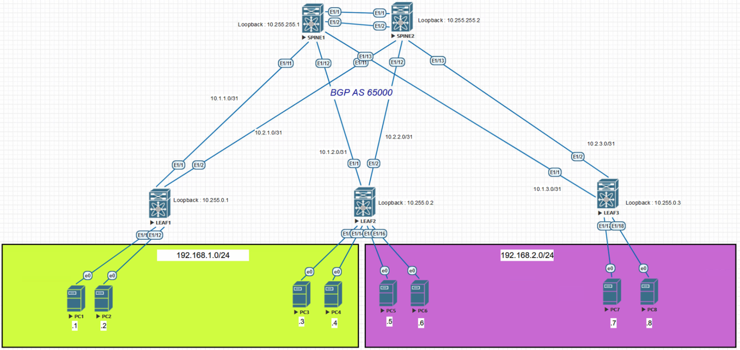
Here is the topology I’m using :
 If you want to learn more about BGP EVPN and VXLAN, I can recommend the Network Direction Youtube Channel, and particularly their VxLAN Playlist :
Now that it is out of the way, let’s focus on configuration. We will be using NX-OS 9.2(2), on the Nexus 9000v platform, in my EVE-NG lab.
Underlay configuration
The first thing we need is a working underlay network.
We will use basic OSPF for this (for configuration scalability, we also often use unnumbered OSPF, but this is out of the scope of this blog post).
Please Note that I will not publish every switch configuration, because I want my readers to think, and not just copy-paste text.😉
SPINE1
hostname SPINE1
feature ospf

router ospf 1
  router-id 10.255.255.1
  log-adjacency-changes
  auto-cost reference-bandwidth 100000 Mbps

interface Ethernet1/11
  no switchport
  ip address 10.1.1.1/31
  ip ospf network point-to-point
  ip router ospf 1 area 0.0.0.0
  no shutdown

interface Ethernet1/12
  no switchport
  ip address 10.1.2.1/31
  ip ospf network point-to-point
  ip router ospf 1 area 0.0.0.0
  no shutdown

interface Ethernet1/13
  no switchport
  ip address 10.1.3.1/31
  ip ospf network point-to-point
  ip router ospf 1 area 0.0.0.0
  no shutdown

interface loopback0
  ip address 10.255.255.1/32
  ip router ospf 1 area 0.0.0.0
LEAF1
hostname LEAF1
feature ospf

router ospf 1
  router-id 10.255.0.1
  log-adjacency-changes
  auto-cost reference-bandwidth 100000 Mbps

interface loopback0
  ip address 10.255.0.1/32
  ip router ospf 1 area 0.0.0.0

interface Ethernet1/1
  no switchport
  ip address 10.1.1.0/31
  ip ospf network point-to-point
  ip router ospf 1 area 0.0.0.0
  no shutdown

interface Ethernet1/2
  no switchport
  ip address 10.2.1.0/31
  ip ospf network point-to-point
  ip router ospf 1 area 0.0.0.0
  no shutdown

interface loopback0
  ip address 10.255.255.1/32
  ip router ospf 1 area 0.0.0.0
You probably noticed a few things :
- We are using the OSPF “point-to-point” type. This is to avoid unnecessary DR/BDR election
- The reference bandwidth has been set to 100Gbps, this is a typical datacenter scenario here.
We also typically put the loopback as an OSPF passive interface. I did not do it here, because it’s a lab environment and the configuration file is already long enough.
Underlay Verification
We need to check that everything works from the underlay before moving on.
First we need to check the OSPF adjacencies :
SPINE1# show ip ospf neighbors
 OSPF Process ID 1 VRF default
 Total number of neighbors: 3
 Neighbor ID     Pri State            Up Time  Address         Interface
 10.255.0.1        1 FULL/ -          03:54:04 10.1.1.0        Eth1/11
 10.255.0.2        1 FULL/ -          03:54:01 10.1.2.0        Eth1/12
 10.255.0.3        1 FULL/ -          03:54:10 10.1.3.0        Eth1/13
Then, we are checking the proper communication between the spine and the leaves
SPINE1# ping 10.255.0.1 source-interface loopback 0 count 2
PING 10.255.0.1 (10.255.0.1): 56 data bytes
64 bytes from 10.255.0.1: icmp_seq=0 ttl=254 time=4.147 ms
64 bytes from 10.255.0.1: icmp_seq=1 ttl=254 time=2.997 ms

SPINE1# ping 10.255.0.2 source-interface loopback 0 count 2
PING 10.255.0.2 (10.255.0.2): 56 data bytes
64 bytes from 10.255.0.2: icmp_seq=0 ttl=254 time=3.922 ms
64 bytes from 10.255.0.2: icmp_seq=1 ttl=254 time=2.356 ms

SPINE1# ping 10.255.0.3 source-interface loopback 0 count 2
PING 10.255.0.3 (10.255.0.3): 56 data bytes
64 bytes from 10.255.0.3: icmp_seq=0 ttl=254 time=2.941 ms
64 bytes from 10.255.0.3: icmp_seq=1 ttl=254 time=3.659 ms
We finish our testing with a traceroute, showing that we are indeed two hops away from SPINE2
SPINE1# traceroute 10.255.255.2 source-interface loopback 0
traceroute to 10.255.255.2 (10.255.255.2) from 10.255.255.1 (10.255.255.1), 30 hops max, 40 byte packets
 1  10.1.1.0 (10.1.1.0)  3.591 ms  3.323 ms  4.003 ms
 2  10.255.255.2 (10.255.255.2)  4.227 ms  4.18 ms  4.253 ms
Now, let’s move to the good stuff, the Overlay !
Overlay Configuration
This is where it gets interesting.
We need to enable the following features on all equipment :
feature bgp
feature interface-vlan
feature vn-segment-vlan-based
feature fabric forwarding
feature nv overlay
nv overlay evpn
We have to configure a full BGP EVPN reachability for all Nexus switches.
Here is the example of SPINE1. The configuraton is similar for all equipments, since only the router-id and neighbors change.
router bgp 65000
  router-id 10.255.255.1
  neighbor 10.255.0.1
    remote-as 65000
    update-source loopback0
    address-family l2vpn evpn
      send-community
      send-community extended
  neighbor 10.255.0.2
    remote-as 65000
    update-source loopback0
    address-family l2vpn evpn
      send-community
      send-community extended
  neighbor 10.255.0.3
    remote-as 65000
    update-source loopback0
    address-family l2vpn evpn
      send-community
      send-community extended
  neighbor 10.255.255.2
    remote-as 65000
    update-source loopback0
    address-family l2vpn evpn
      send-community
      send-community extended
Please note that in a typical datacenter, the spines are route-reflectors. We are simplifying things a bit for better readability (but the configuration is longer because we need all the iBGP neighbors).
Leaf-Specific Config
Since the spines are NOT used for hosts, there is no need for an anycast gateway, and therefore no need to configure anything related to the anycast gateway
The leaves will be the only switches that handles direct host connections, and will then assume the role of VTEP and gateway.
I need to configure the anycast gateway mac on my leaves : I’m using mac addresses 0000.1111.1111, 0000.1111.2222 and 0000.1111.3333 . In a real world scenario, be careful not to assign a mac address that is already assigned to a host (or will in the future).
fabric forwarding anycast-gateway-mac XXXX.XXXX.XXXX
We will also configure the VTEP via the NVE interface.
interface nve1
  no shutdown
  host-reachability protocol bgp
  source-interface loopback0
BGP verification
You will notice that your typical show ip bgp summary does not return any information about your neighbors. It is an expected behavior since you are peering on the “evpn” address family.
To check your neighbors, you need to type the show bgp l2vpn evpn summary
SPINE1# show bgp l2vpn evpn summary
*** truncated output***
Neighbor        V    AS MsgRcvd MsgSent   TblVer  InQ OutQ Up/Down  State/PfxRcd
10.255.0.1      4 65000     221     221        6    0    0 03:35:17 0
10.255.0.2      4 65000     219     219        6    0    0 03:34:01 0
10.255.0.3      4 65000     218     218        6    0    0 03:32:32 0
10.255.255.2    4 65000     226     226        6    0    0 03:40:34 0
We see here the proper establishment of the neighboring relationship, but we are still not sending or receiving any prefix/mac. For this part to work, we need to work on the full configuration of the VNI, VRF, VLANs, and gateways.
VNI, VRF, VTEP and Gateway Configuration
This is the hardest part to understand for anyone that has never deployed VXLAN with BGP EVPN.
The following features will be deployed :
- L3VNI
- VRF
- RD and RT
- VTEP
- ARP Suppression
- Head-end Replication
- Anycast Gateway
- EVPN
Please note that you don’t need to configure anything on the Spines anymore at this point, since the VTEPs are the leaves !
L3VNI
Basically, in a datacenter environment, we will have “Tenants” or “Customers”. We want every customer/tenant to be isolated in its own VRF.
In our simple example, we only have 1 customer, so we will create only one VRF.
For each VRF, we need a “L3VNI” for routing between each Subnet (in our case between 192.168.1.0/24 and 192.168.2.0/24).
The first step is to create a “routing vlan” or “L3VNI” (since each of our VXLAN will be associated with a VLAN).
To simplify the L3VNI part, we will use the same VLAN ID than the VXLAN VNI. Keep in mind that it is not mandatory at all (and that you can have 2^24 VNIs, as opposed to 2^12 VLANs).
So, we first create a VLAN that we associate with a VNI :
vlan 10
  vn-segment 10
Then, we create our VRF and associate our VNI number with it:
vrf context VRF10
  vni 10
  rd auto
  address-family ipv4 unicast
    route-target both auto
    route-target both auto evpn
After that, we create our L3VNI routing SVI :
interface vlan 10
  vrf member VRF10
  no shutdown
  ip forward
Please note the “ip forward” command that allows it to do routing even without an ip address.
We then tell our VTEP to associate the VNI number 10 to our VRF.
interface nve1
  member vni 10 associate-vrf
The L3VNI part is over, we can now create our Bridge Domains (aka L2VNI)
L2VNI
On LEAF1, we will create a locally-signifiant VLAN1111, with a fabric-wide VXLAN 111111. This is the VXLAN that we will use for our 192.168.1.0/24 network.
vlan 1111
  vn-segment 111111
To use BGP, we need to inform the VTEP to do 2 things :
- Suppress ARP traffic
-
Announce and receive mac addresses via BGP
interface nve1 member vni 111111 suppress-arp ingress-replication protocol bgp
We then need to create our anycast-gateway (for inter-VXLAN routing basically)
interface vlan 1111
  no shutdown
  vrf member VRF10
  ip address 192.168.1.254/24
  fabric forwarding mode anycast-gateway
And we finish the config by telling evpn (so bgp) to announce this VNI with automatically defined RD and RT (best-practice for a Cisco-Only fabric).
evpn
  vni 111111 l2
    rd auto
    route-target import auto
    route-target export auto
And we finish by configuring the access ports (like we’ve been doing forever)
interface Eth1/11-2
  switchport mode access
  switchport access vlan 1111
  no shutdown
We need to do the same thing on LEAF2 and LEAF3 at this point.
Do not forget that the VNI is a fabric-wide identifier, and that the VLAN is only local to the switch. It means that as soon as you configure the proper 111111 VNI, you can assign it to any VLAN. This is what allow you to scale a lot more with VXLAN.
Please note that on old version of NX-OS, we also needed to configure the following statement :
router bgp 65000
  vrf VRF10
    address-family ipv4 unicast
      advertise l2vpn evpn
There is no need to do that anymore. If you do it on the newer Nexus platform, you will get the following message : Command 'advertise l2vpn evpn' has been deprecated and no longer has any effect. I’m just putting it here for reference for the folks that still use old versions of NX-OS.
We are done with the configuration ! We just need to check that everything works properly now.
Final Verification and useful commands
Verifications
The first thing we need to do is to check the communication between our hosts.
We can see there is no issue communicating with a host on the same switch (we are here using the traditionnal VLAN behavior, no VXLAN or BGP is needed).
root@PC1:~# ping 192.168.1.2 -c 2
PING 192.168.1.2 (192.168.1.2) 56(84) bytes of data.
64 bytes from 192.168.1.2: icmp_seq=1 ttl=64 time=5.15 ms
64 bytes from 192.168.1.2: icmp_seq=2 ttl=64 time=4.33 ms
We are also able to ping another host using the same VXLAN, on another switch.
root@PC1:~# ping 192.168.1.4 -c 2
PING 192.168.1.4 (192.168.1.4) 56(84) bytes of data.
64 bytes from 192.168.1.4: icmp_seq=1 ttl=64 time=11.0 ms
64 bytes from 192.168.1.4: icmp_seq=2 ttl=64 time=11.0 ms
Here is the interesting stuff : we are able to ping a host that is on another switch, and on another VXLAN, using our anycast gateway and L3VNI !
root@PC1:~# ping 192.168.2.8 -c 2
PING 192.168.2.8 (192.168.2.8) 56(84) bytes of data.
64 bytes from 192.168.2.8: icmp_seq=1 ttl=62 time=15.4 ms
64 bytes from 192.168.2.8: icmp_seq=2 ttl=62 time=15.4 ms
Useful commands
LEAF1# show nve vrf
VRF-Name     VNI        Interface Gateway-MAC
------------ ---------- --------- -----------------
VRF10        10         nve1      5000.0003.0007


LEAF1# show nve vni
Codes: CP - Control Plane        DP - Data Plane
*** truncated output ***
Interface VNI      Multicast-group   State Mode Type [BD/VRF]      Flags
--------- -------- ----------------- ----- ---- ------------------ -----
nve1      10       n/a               Up    CP   L3 [VRF10]
nve1      111111   UnicastBGP        Up    CP   L2 [1111]


LEAF1# show nve peers
Interface Peer-IP          State LearnType Uptime   Router-Mac
--------- ---------------  ----- --------- -------- -----------------
nve1      10.255.0.2       Up    CP        01:02:33 5000.0004.0007
nve1      10.255.0.3       Up    CP        00:03:34 5000.0005.0007


LEAF1# show vxlan
Vlan            VN-Segment
====            ==========
10              10
1111            111111


LEAF1# show l2route evpn mac all
*** truncated output ***
Topology    Mac Address    Prod   Flags         Seq No     Next-Hops
----------- -------------- ------ ------------- ---------- ----------------
10          5000.0004.0007 VXLAN  Rmac          0          10.255.0.2
10          5000.0005.0007 VXLAN  Rmac          0          10.255.0.3
1111        0050.0000.0600 Local  L,            0          Eth1/11
1111        0050.0000.0700 Local  L,            0          Eth1/12


LEAF2# show l2route evpn mac-ip all
Flags -(Rmac):Router MAC (Stt):Static (L):Local (R):Remote (V):vPC link
(Dup):Duplicate (Spl):Split (Rcv):Recv(D):Del Pending (S):Stale (C):Clear
(Ps):Peer Sync (Ro):Re-Originated
Topology    Mac Address    Host IP         Prod   Flags         Seq No     Next-Hops
----------- -------------- --------------- ------ ---------- ---------------
1111        0050.0000.0600 192.168.1.1     BGP    --            0         10.255
.0.1
1111        0050.0000.0700 192.168.1.2     BGP    --            0         10.255
.0.1
2222        0050.0000.0a00 192.168.2.5     HMM    --            0         Local

2222        0050.0000.0b00 192.168.2.6     HMM    --            0         Local

2222        0050.0000.0c00 192.168.2.7     BGP    --            0         10.255
.0.3
2222        0050.0000.0d00 192.168.2.8     BGP    --            0         10.255
.0.3
There is also the show bgp l2vpn evpn command, but the output is so large that I can’t fit it in here. It is basically the “show me everything” command
EDIT : I can recommend you this amazing cisco live presentation document : https://www.ciscolive.com/c/dam/r/ciscolive/us/docs/2018/pdf/BRKDCN-3040.pdf It goes through a lot of troubleshooting steps for BGP EVPN VXLAN.